Mammoth Hydraulic Cylinder Technical Specifications
Mammoth Hydraulic Cylinder
S250 Series Hydraulic Cylinders
Features
- Hydraulic cylinder type S250 to setup standards have a nominal working pressure of 25,00 MPa.
- Designed to give a high degree of reliability in heavy industrial and mobile applications.
- Ground and chrome plated EN8 rods for longer life on gland seals and shaft surface protection.
- Cylinder barrel ST52 honed to N4 finish for longer seal life.
- Various seal materials are available to suit the hydraulic medium.
- Various rod materials available to suit applications.
- Alternative ports & port positions available.
Technical Data
- Nominal Pressure - 25,0 MPa (250 bar 3625 psi)
- Static Test Pressure - 37,0 MPa (370 bar 5440 psi)
- Mounting Position - Optional
- Hydraulic Fluid - Mineral Oil To DIN 51 524
- Fluid Temp. Range - -20˚C to +80˚C
- Stroking Speed - Up to 0,5 m/s
- Mountings - As per S250 series
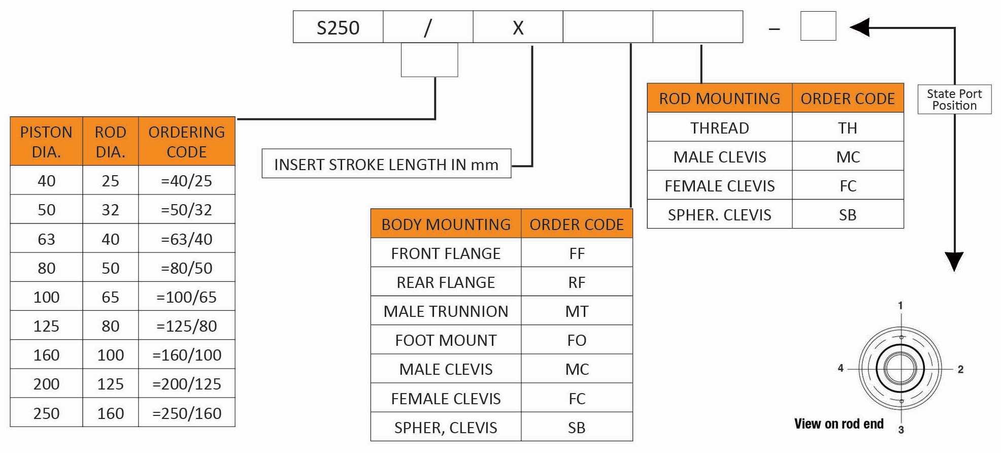
Ordering Code Cylinder Type: S250
Force Diagram in kN
| S250 SERIES | 10 MPa 100 BAR 1450 PSI | 15 MPa 150 BAR 2175 PSI | 21 MPa 210 BAR 3050 PSI | 25 MPa 250 BAR 3650 PSI |
||||
|---|---|---|---|---|---|---|---|---|
| CYL. SIZE | PUSH | PULL | PUSH | PULL | PUSH | PULL | PUSH | PULL |
| 40/25 | 12.5 | 7.6 | 18.5 | 11.4 | 26.3 | 16.0 | 31.4 | 19.1 |
| 50/32 | 19.6 | 11.6 | 29.5 | 17.4 | 41.0 | 24.0 | 49.0 | 29.0 |
| 63/40 | 31.0 | 18.6 | 46.8 | 28.0 | 65.5 | 39.0 | 78.0 | 46.5 |
| 80/50 | 50.0 | 30.6 | 75.4 | 46.0 | 105.6 | 64.0 | 125.7 | 76.6 |
| 100/65 | 78.5 | 45.4 | 117.8 | 68.0 | 165.0 | 95.0 | 196.4 | 113.4 |
| 125/80 | 122.7 | 72.5 | 184.0 | 108.7 | 257.7 | 152.0 | 307.0 | 181.0 |
| 160/100 | 201.0 | 122.5 | 301.6 | 183.8 | 422.0 | 257.0 | 502.7 | 306.0 |
| 200/125 | 314.0 | 191.4 | 471.0 | 287.0 | 659.7 | 402.0 | 785.4 | 478.6 |
| 250/160 | 491.0 | 289.8 | 736.0 | 434.7 | 1030.8 | 608.6 | 1227.0 | 724.5 |
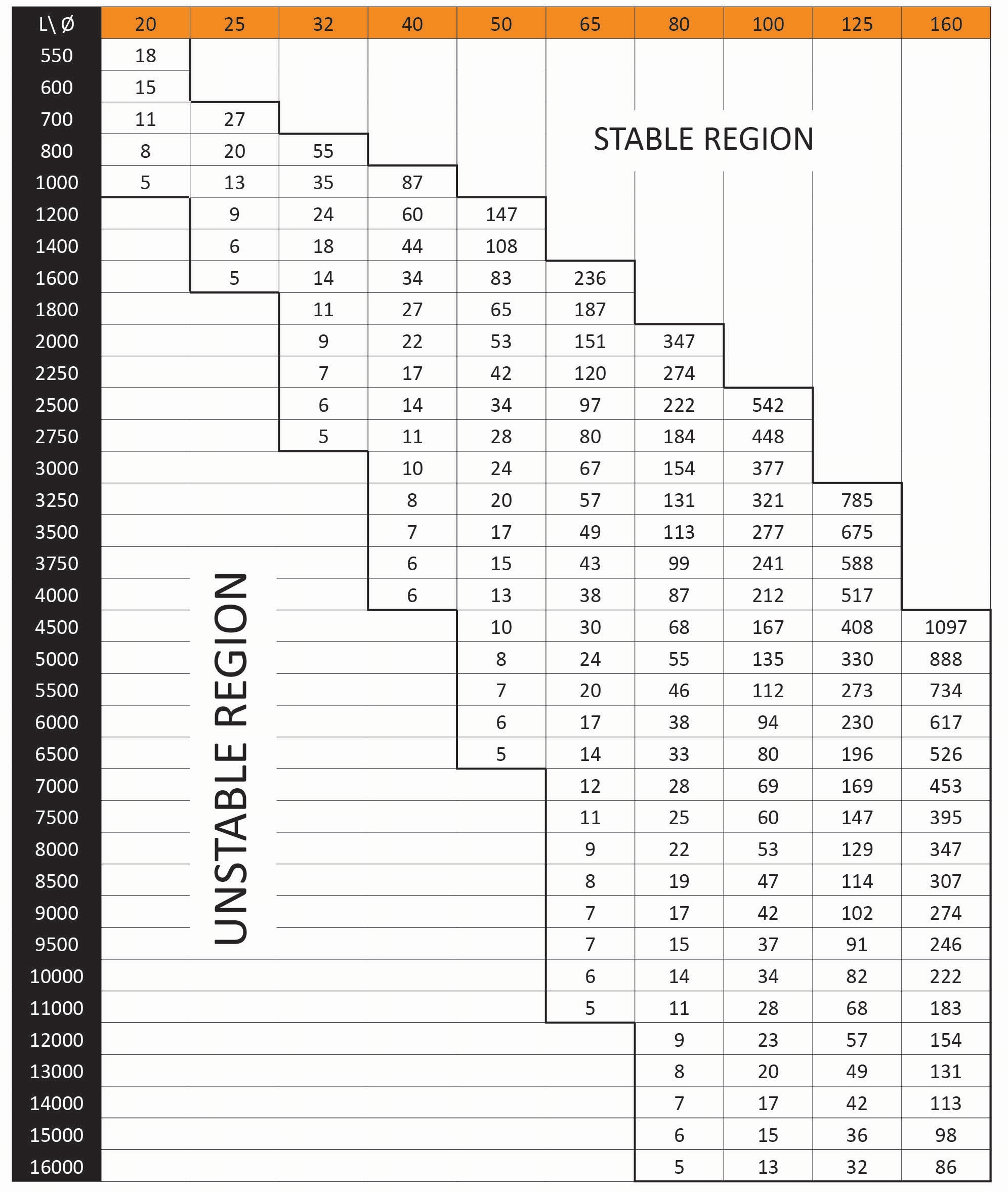
Buckling Table Piston Rod Column Loading Chart Load-F-IN KN
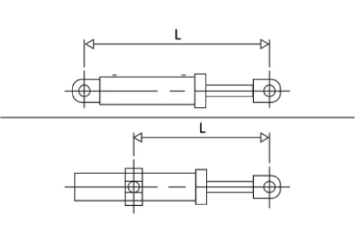
Class “A“ Mounting. Both Ends Rounded Or Pinned. Use Load Figure Shown in Chart.
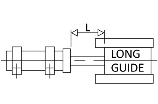
Class “C” Mounting. Both Ends Fixed (Straight in Line Motion). Multiply Load Figure X 4.
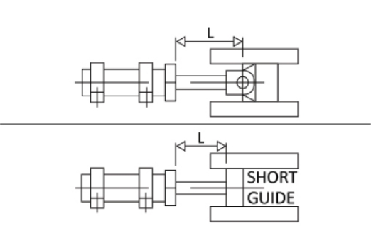
Class “B” Mounting. One End Fixed. Other Rounded Or Pinned (Straight in Line Motion). Multiply Load Figure X2.
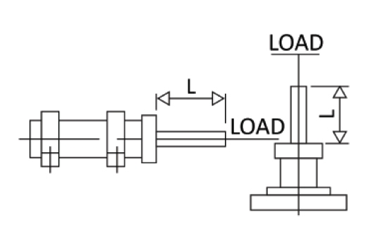
Class “D” Mounting. One End Fixed; One End Free (Concentric Loading Multiply Load Figure X 0.25
Diam. and Length in mm - Load Figures in kN - Safety Factor 3.1
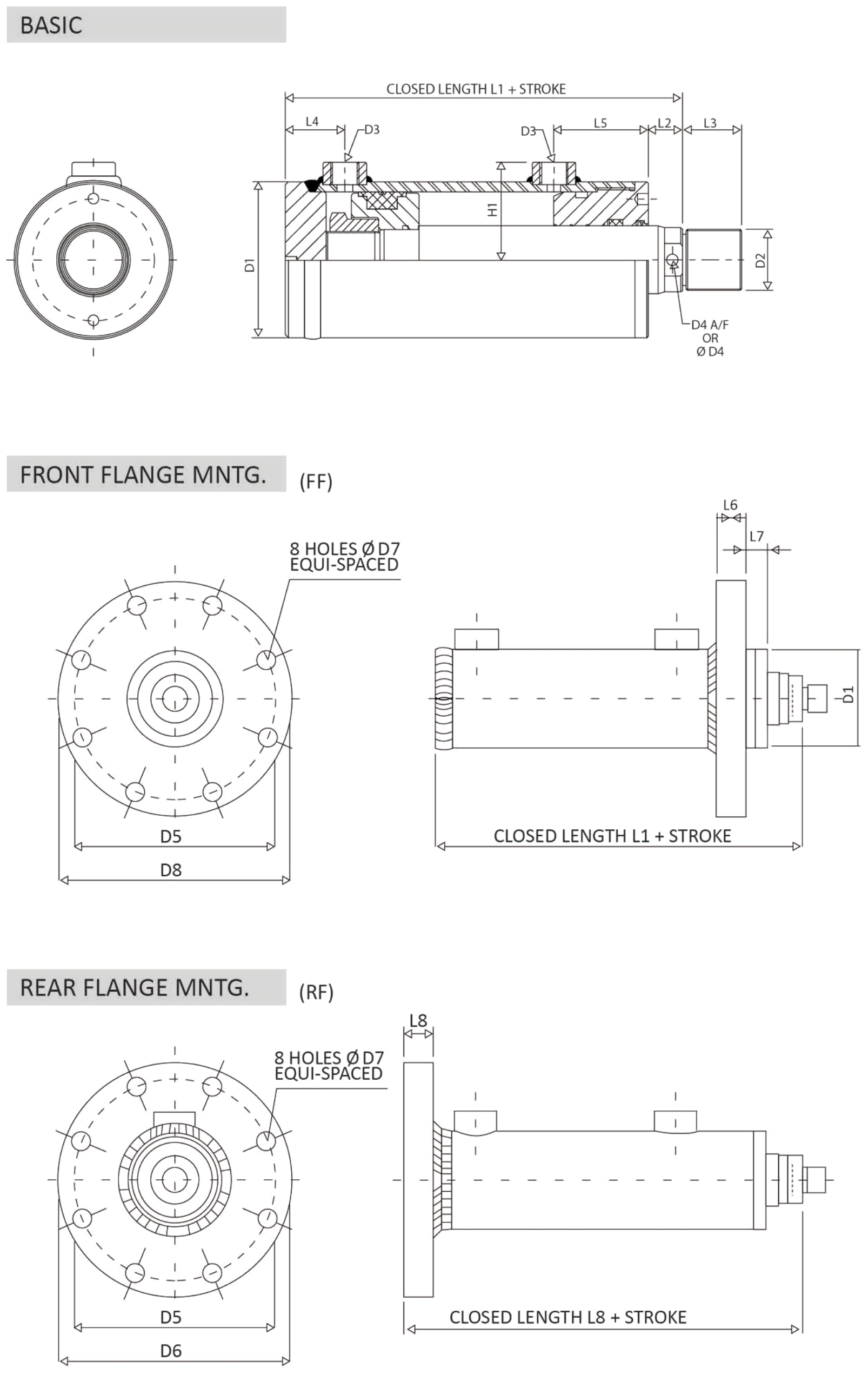
| CYL. SIZE | B1 | B2 | B3 | B4 | B5 | B6 | B7 | B8 | B9 | B10 | B11 | D1 | D2 | D3 | D4 | D5 |
|---|---|---|---|---|---|---|---|---|---|---|---|---|---|---|---|---|
| 40/25 | 90 | 130 | 25 | 110 | 140 | 20 | 35 | 22 | 50 | 16 | 19 | 50 | M16x1.5 | 3/8"BSP-P | 19 A/F | 120 |
| 50/32 | 105 | 145 | 30 | 115 | 145 | 25 | 35 | 26 | 55 | 20 | 23 | 60 | M16x1.5 | 3/8"BSP-P | 24 A/F | 126 |
| 63/40 | 120 | 170 | 40 | 135 | 165 | 32 | 50 | 33 | 72 | 22 | 28 | 75 | M22x1.5 | 3/8"BSP-P | 36 A/F | 145 |
| 80/50 | 135 | 199 | 50 | 150 | 185 | 40 | 60 | 41 | 90 | 28 | 35 | 92 | M35x1.5 | 1/2"BSP-P | 36 A/F | 165 |
| 100/65 | 160 | 240 | 60 | 190 | 225 | 50 | 65 | 51 | 111 | 35 | 40 | 115 | M45x1.5 | 1/2"BSP-P | Ø 10 | 200 |
| 125/80 | 195 | 295 | 75 | 235 | 275 | 60 | 80 | 61 | 131 | 44 | 50 | 145 | M58x1.5 | 3/4"BSP-P | Ø 10 | 235 |
| 160/100 | 240 | 366 | 100 | 280 | 320 | 80 | 100 | 81 | 171 | 55 | 60 | 185 | M80x2 | 3/4"BSP-P | Ø 10 | 280 |
| 200/125 | 295 | 455 | 120 | 340 | 385 | 100 | 140 | 101 | 211 | 70 | 74 | 230 | M110x2 | 1"BSP-P | Ø 10 | 340 |
| 250/160 | 370 | 570 | 150 | 420 | 480 | 125 | 160 | 126 | 260 | 85 | 90 | 290 | M130x3 | 1.1/4"BSP-P | Ø 12 | 420 |
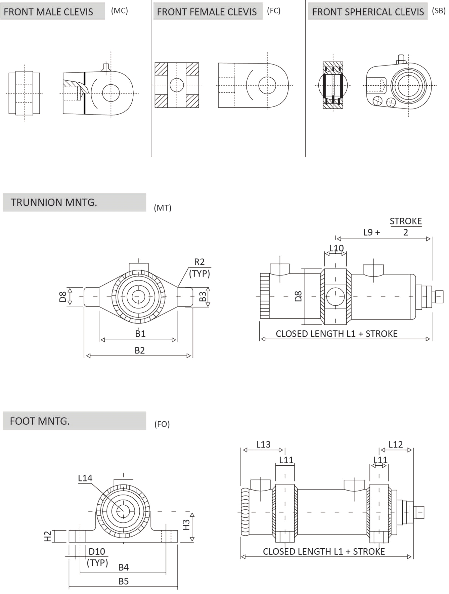
| CYL. SIZE | D6 | D7 | D8 | D9 | D10 | D11 | D12 | D13 | H1 | H2 | H3 | L1 | L2 | L3 | L4 | L5 | L6 | L7 | L8 |
|---|---|---|---|---|---|---|---|---|---|---|---|---|---|---|---|---|---|---|---|
| 40/25 | 140 | 11 | 20 | 64 | 13 | 20 | 20 | 25 | 40 | 12 | 35 | 122 | 15 | 15 | 27 | 50 | 18 | 11 | 140 |
| 50/32 | 145 | 11 | 25 | 74 | 13 | 25 | 25 | 25 | 45 | 15 | 40 | 147 | 20 | 15 | 27 | 55 | 18 | 14 | 165 |
| 63/40 | 170 | 14 | 32 | 90 | 13 | 32 | 32 | 32 | 52 | 15 | 50 | 157 | 22 | 21 | 34 | 55 | 20 | 14 | 177 |
| 80/50 | 200 | 18 | 40 | 110 | 17 | 40 | 40 | 49 | 61 | 20 | 55 | 177 | 22 | 34 | 42 | 60 | 24 | 14 | 201 |
| 100/65 | 240 | 22 | 50 | 135 | 17 | 50 | 50 | 61 | 72 | 20 | 70 | 194 | 25 | 44 | 44 | 70 | 28 | 14 | 222 |
| 125/80 | 270 | 22 | 63 | 170 | 21 | 60 | 60 | 75 | 90 | 25 | 85 | 226 | 25 | 55 | 57 | 80 | 34 | 14 | 260 |
| 160/100 | 320 | 22 | 80 | 215 | 21 | 80 | 80 | 102 | 110 | 25 | 110 | 241 | 28 | 68 | 67 | 80 | 38 | 14 | 279 |
| 200/125 | 385 | 26 | 100 | 270 | 25 | 100 | 100 | 138 | 133 | 35 | 140 | 290 | 30 | 95 | 76 | 100 | 42 | 20 | 332 |
| 250/160 | 480 | 33 | 125 | 335 | 32 | 125 | 120 | 172 | 167 | 35 | 175 | 365 | 35 | 110 | 90 | 114 | 56 | 20 | 421 |
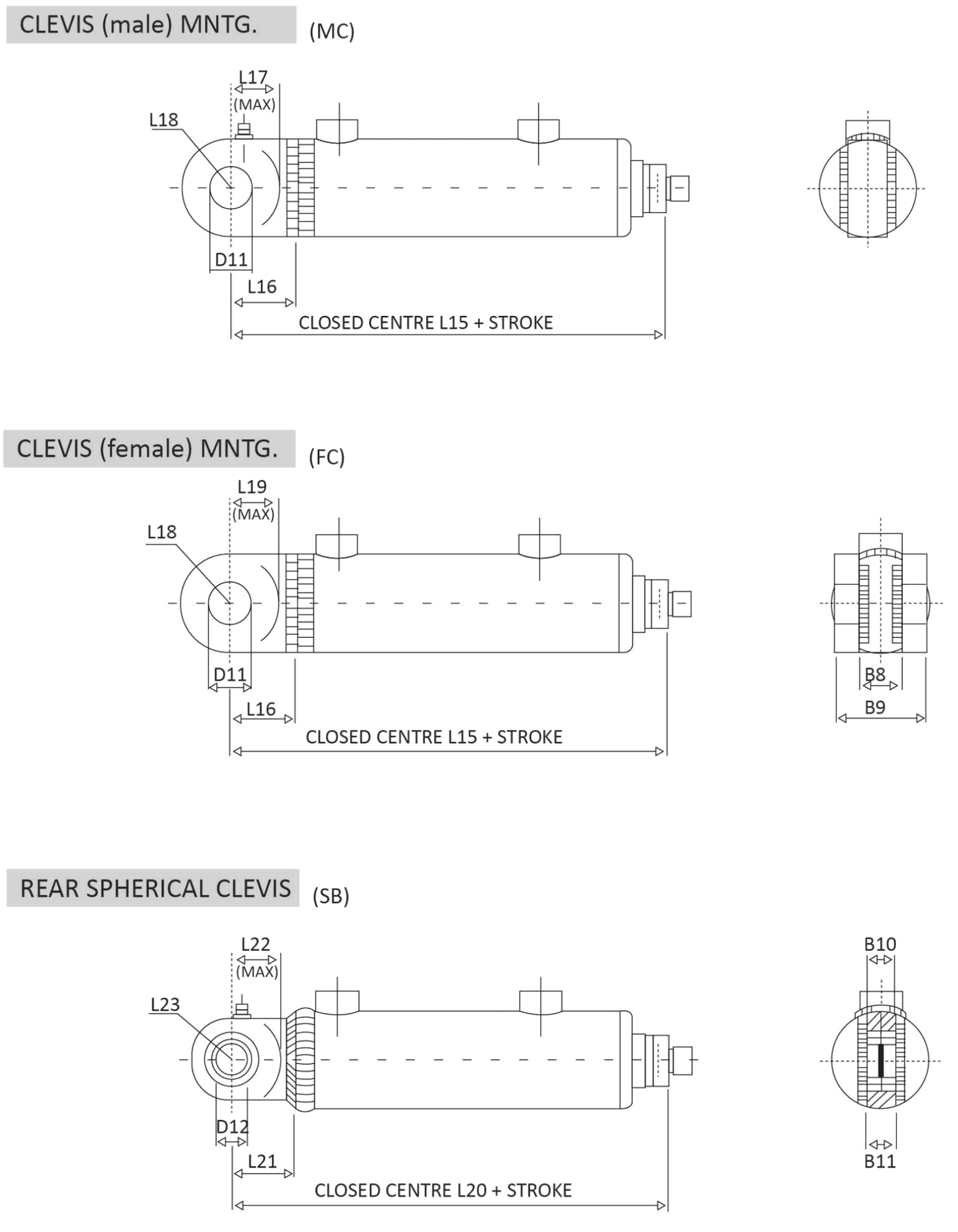
| CYL. SIZE | L9 | L10 | L11 | L12 | L13 | L14 | L15 | L16 | L17 | L18 | L19 | L20 | L21 | L22 | L23 | L24 | L25 | L26 | L27 | L28 |
|---|---|---|---|---|---|---|---|---|---|---|---|---|---|---|---|---|---|---|---|---|
| 40/25 | 110 | 25 | 25 | 46 | 60 | 33 | 162 | 40 | 32 | 25 | 32 | 160 | 38 | 32 | 25 | 55 | 30 | 25 | 50 | 28 |
| 50/32 | 110 | 30 | 25 | 46 | 60 | 38 | 187 | 40 | 32 | 30 | 32 | 192 | 45 | 38 | 27.5 | 60 | 35 | 25 | 50 | 28 |
| 63/40 | 118 | 40 | 30 | 48 | 65 | 45 | 202 | 45 | 37 | 35.5 | 37 | 208 | 51 | 43 | 32.5 | 70 | 40 | 30 | 60 | 32 |
| 80/50 | 130 | 50 | 40 | 52 | 80 | 55 | 237 | 60 | 50 | 45 | 50 | 246 | 69 | 59 | 50 | 95 | 55 | 45 | 85 | 47 |
| 100/65 | 150 | 60 | 50 | 60 | 90 | 68 | 264 | 70 | 60 | 50 | 60 | 282 | 88 | 78 | 61.5 | 115 | 65 | 55 | 105 | 58 |
| 125/80 | 165 | 75 | 60 | 66 | 115 | 85 | 306 | 80 | 65 | 65 | 65 | 326 | 100 | 85 | 70 | 135 | 75 | 65 | 130 | 65 |
| 160/100 | 185 | 100 | 70 | 75 | 125 | 108 | 341 | 100 | 85 | 80 | 85 | 382 | 141 | 126 | 90 | 170 | 95 | 80 | 170 | 88 |
| 200/125 | 175 | 110 | 80 | 85 | 150 | 135 | 420 | 130 | 110 | 100 | 110 | 460 | 170 | 150 | 125 | 235 | 120 | 105 | 235 | 115 |
| 250/160 | 200 | 140 | 100 | 90 | 175 | 168 | 525 | 160 | 135 | 125 | 135 | 575 | 210 | 185 | 180 | 280 | 145 | 140 | 310 | 170 |
